Hardware
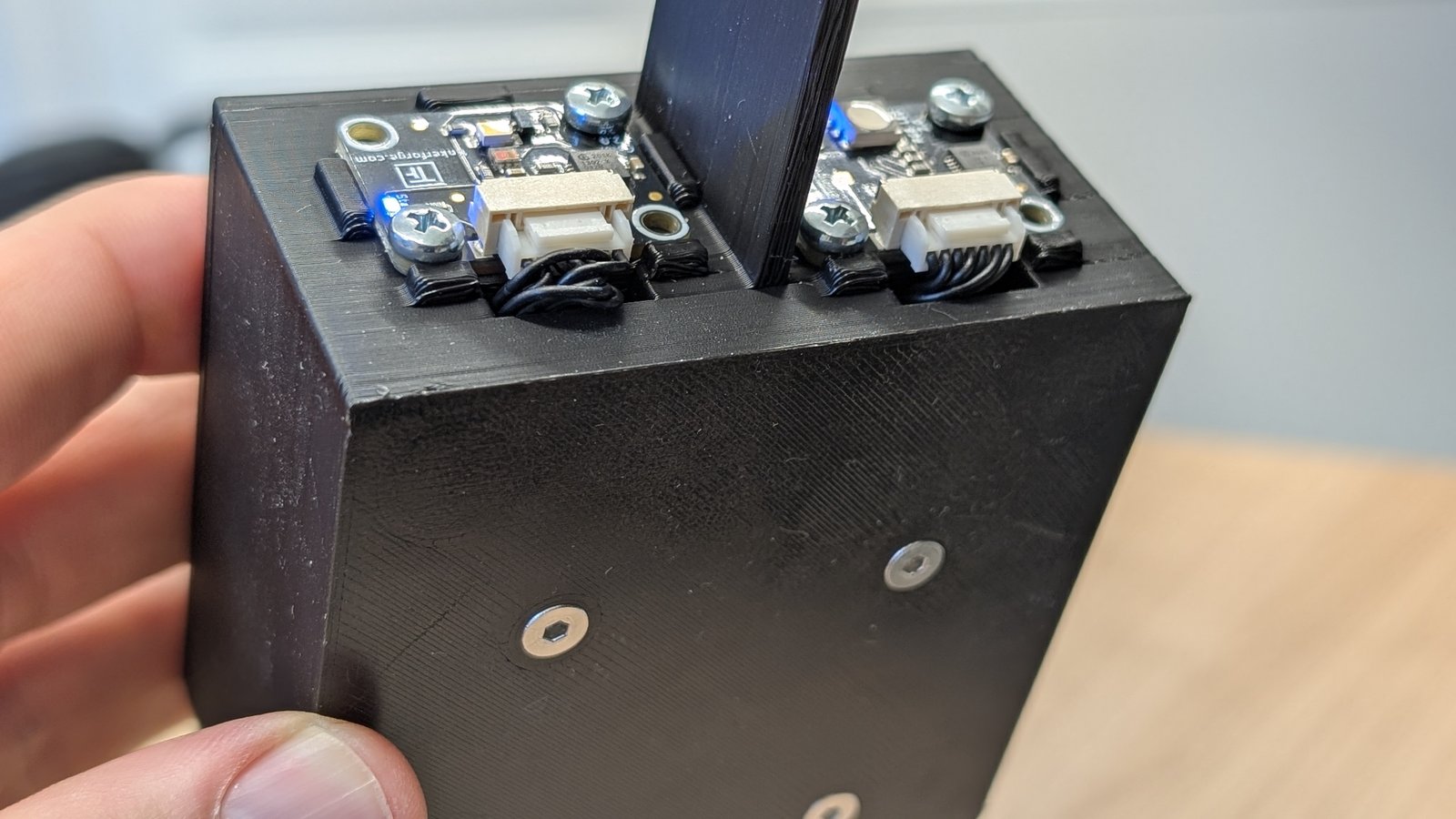
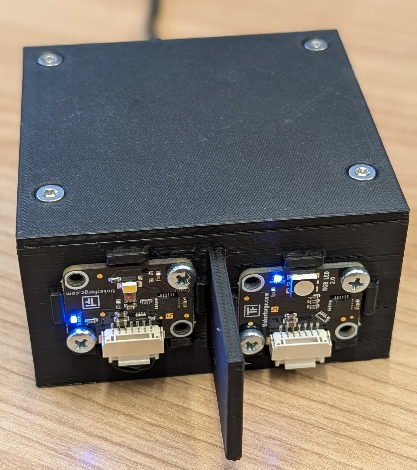
Your device is three parts in a 3D-printed case:
- an RGB LED Bricklet 2.0, the lamp that sends,
- a Color Bricklet 2.0, the eye that receives,
- a Master Brick, the small controller board that connects both to your laptop over USB.
All three come from Tinkerforge, a German maker of modular electronics. The two small boards, the Bricklets, sit on the front of the case, the Master Brick inside.
You and your partner get two of these devices, one each. Between you, you hold both ends of the link.
The two devices stand on the table facing each other. Because lamp and eye sit symmetrically to the middle of the front, turning one device around puts its lamp in front of the other’s eye, and its eye in front of the other’s lamp. A short wall between the two, the septum, keeps your own lamp out of your own eye.
Something follows from this that you will only need late in the project: since every device can send and receive, the link works in both directions. Up to and including Challenge 3 you use only one direction all the same. The way back is opened in Challenge 4.
The LED
What looks like one lamp is really three: a red one, a green one and a blue one, packed so closely together that your eye cannot separate them. You tell each of the three how brightly to shine, as a number from 0 (off) to 255 (full brightness). Because they sit so close, you do not see three lights but one mixed colour.
Three numbers, then, and every combination you can reliably recognise on the other side is a sign you can send. Red at full brightness with the other two off gives you red. All three at full gives you white. All three at zero is dark. Red at full with a little blue mixed in is a colour that has no everyday name, and it is just as good a sign as the others, provided the eye across the table can tell it from its neighbours.
How fast the LED can switch from one colour to the next, and what the sensor sees during the switch, is not written in any datasheet you should trust. It is one of the first things worth measuring.
The colour sensor
What the sensor actually measures
In front of the sensor sit tiny colour filters. One lets through mostly red light, one mostly green, one mostly blue. Behind each filter the light that gets through is counted. So you get three numbers that say how much red, green and blue is falling on the sensor right now.
The word “mostly” matters. The filters do not separate cleanly. Some green light gets through the red filter too. That is why red light does not give you one high number and two zeros. All three values are above zero, just in different proportions.
Four channels, not three
Next to the three colour values there is a fourth, the clear channel. It sits behind no filter and simply counts all the light. That makes it more sensitive than the other three, and often the most useful of the four when all you want to tell apart is brightness.
So every reading is four numbers: red, green, blue, clear. Keep the fourth one in view. Many teams ignore it and give away signal for nothing.
The lamp on the sensor board
The sensor board carries a small white lamp of its own. It is meant for measuring the colour of surfaces, where you have to light the object first. For your device it is a source of stray light and nothing else. Leave it off.
Integration time and gain
The sensor has two settings, and they are the central trade-off of the whole project.
The integration time is how long the sensor collects light before it reports a number. You can choose between five values, from about 2 milliseconds to 700 milliseconds. A long time gives calm, steady numbers, because random flicker averages out. It also means fewer readings per second: at 700 milliseconds you get little more than one reading a second, and your symbols cannot come faster than that. A short time gives many readings per second, but each one is noisier.
The gain is how strongly the sensor amplifies what it collects. You can choose between four steps, from 1 to 60. A high gain makes a weak signal visible, but it also makes the numbers hit the top of their range sooner, at which point bright and very bright look the same.
Out of the box the module lifi_hardware sets a medium-long integration time and a gain of 16, which is a safe place to start and almost certainly not where you will end up. The two settings are deliberately easy to change, and you should change them and measure what happens. The page on the module shows where.
The numbers do not come back the way you sent them
When you give the LED the values (255, 0, 60), the sensor reports something completely different. That is not a bug. Its numbers depend not only on the light that was sent but also on how far away it is, how bright the room is, and how you have set gain and integration time. There is no way to calculate backwards. How you transmit reliably all the same is the subject of Challenge 1.
Optical setup
Between the two devices you may build things yourself, and you should: tubes, apertures, reflectors, lenses. A good light channel is one of the most effective levers in the whole project.
Rules
Allowed is anything passive: pipes, cardboard, paint, aluminium foil, mirrors, lenses, acrylic rods, clamps, stands, 3D-printed parts.
Not allowed are additional sensors, additional light sources, lasers, or swapping out the LED or the colour sensor.
Budget: building is optional, and if your team builds, the material may be worth at most 10 euros, which you pay yourselves because there is no reimbursement. Document what you built with a photo and a short explanation of why you built it that way.
The fixed distance
The distance between the front of the lamp and the front of the eye is fixed and the same for everyone. It is chosen so that a bare device just about works and a good light channel makes a real difference.
Before you buy anything
First measure what your setup manages without any aids. In our experience an inside wall painted matt black does more than a bought lens.
The case
The case is 3D-printed in two parts: the tray, with the front wall built in, and the lid. The source is a parametric OpenSCAD file: lifi-device-case.scad. It is released under CC0, so you may use and change it without any conditions.

Parts list
Everything that goes into one device. The kits come assembled. You need the list when something has to be replaced or you want to build a device of your own.
| Qty | Part | Note |
|---|---|---|
| 1 | Master Brick (Tinkerforge) | connects the Bricklets to the laptop over USB-C; documentation |
| 1 | RGB LED Bricklet 2.0 | the sender; documentation |
| 1 | Color Bricklet 2.0 | the receiver, measures red, green, blue and clear; documentation |
| 2 | Bricklet cable, 7-pin, 15 cm | Bricklets to the Master Brick |
| 1 | USB-A to USB-C cable, 100 cm (Tinkerforge) | device to laptop; any other USB-C data cable works too |
| 1 | Mounting kit 12 mm (Tinkerforge) | all the small parts for Brick and Bricklets: the four 10 mm spacers (threaded inside at both ends) for the Master Brick, eight M3 screws (four for the Bricklets at the front, four for the Brick on the spacers), eight nuts and washers |
| 4 | Screw M3 × 8, countersunk, DIN 965 (search) | from below through the floor into the spacers; countersunk so the heads sit flush in the recesses (the pan-head screws from the kit would stick out) |
| 4 | Thread-forming screw EJOT Delta PT WN 5454, countersunk 3.0 × 8, Torx (DW Bendler, SW34172) | for the lid; made to form their thread in plastic, not sheet-metal screws |
| 4 | Self-adhesive rubber foot, Ø 10 × 3 mm, black (Delock 18309 at Reichelt, pack of 50) | into the recesses on the underside |
| 2 | Printed parts, tray and lid | STL files below, black matt filament |
The Tinkerforge links go straight to the maker’s shop. The search links for the standard parts are examples; any hardware or electronics shop carries them.
The 3D model
Both printed parts, to look at: drag to turn, scroll to zoom.
To download and print yourself:
Printing
Print the tray with the open side up, the lid flat. Recommended: black, matt filament (PETG or PLA), 0.2 mm layer height, at least 4 perimeters so the screw bosses are solid. Only the septum protruding from the front needs support. Inside there are deliberately no cavities the slicer would have to support.
Assembly
- Screw the four 10 mm spacers from the mounting kit in from below through the floor (M3 × 8 countersunk, the heads disappear into the recesses), then screw the Master Brick onto the spacers from above with four kit screws.
- Set the LED and colour sensor Bricklets into their mounts from the front and fasten each with two kit screws. Hold the kit nuts against them from inside, with your fingers or a small spanner. The inside is still open at this point.
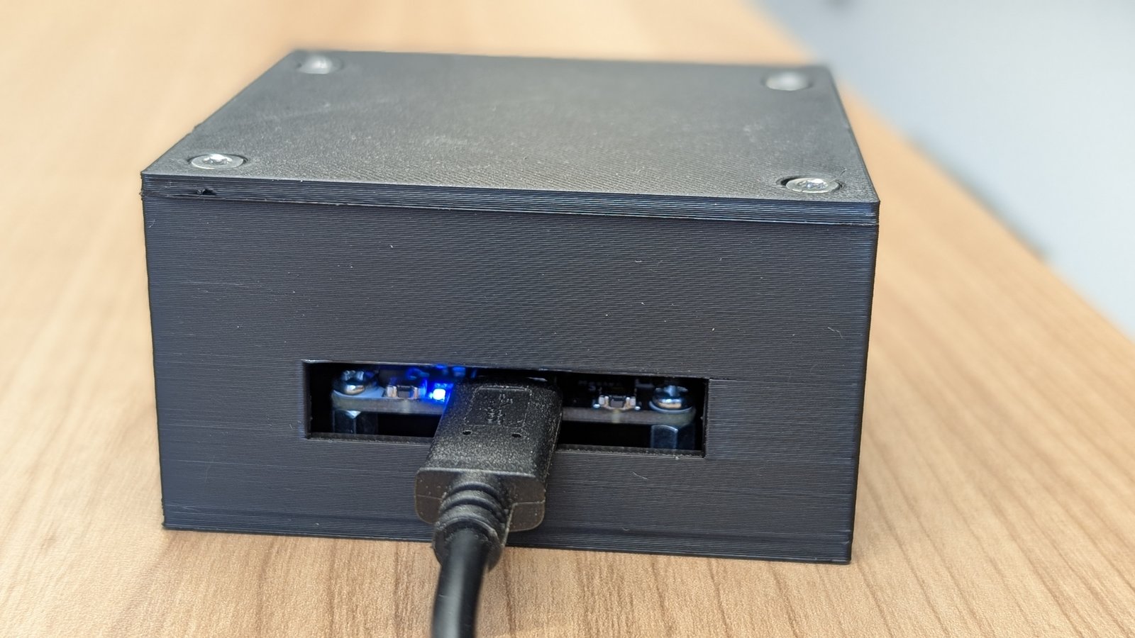
- Run the Bricklet cables through the slots below the mounts to the Master Brick, and plug the USB-C cable in through the slot in the back wall.
- Put the lid on and fasten it with the four thread-forming screws. The very first time, turn them in by hand, not with a power screwdriver: they cut their own thread into the bosses as they go.
- Stick the rubber feet into the four recesses on the underside.